In about 1640 a German engraver by the name of Von Seigen employed a new method called mezzotint and this was used to reproduce paintings in black and white and also in color. Engravers mastered the art of varying the depth of the engraving or etching which allowed differing shades of color to be achieved-exactly the same principle as today's gravure process.
The intaglio process was further developed in the early 17th century when intaglio printing, also known as gravure printing, began to use metal plates which carried the etched image which was then printed onto the substrate.
The invention of photography led to the method of transferring a photo image onto a carbon tissue coated in a light-sensitive gelatine which allowed the etching of an image onto a steel, copper covered cylinder. This was the beginning of the modern rotogravure process. An example of early rotogravure was the introduction of newspaper supplements 1930s –1960s which carried rotogravure printed photographs. Prior to this newspapers had published very few photographs.
GRAVURE PRINTING IN LABELS
Gravure printing has usually been the chosen process most suitable for printing fine tones with a sharp dot formation giving a high quality result and best suited to the long run markets. The self–adhesive label market tends to service the short to medium run markets and the gravure process has never been considered by the label printer as the most suitable.
However the use of gravure in the label industry has been increasing, particularly as the facility to produce highly reflective metallic inks and specialised coatings by the gravure process means that gravure units are now used as individual units on combination label presses. Gravure label presses are now used for both wet glue and self-adhesive label manufacture, particularly for the long run paper and filmic label market.
GRAVURE PRESS CONFIGURATIONS
Gravure press configurations fall into three categories: sheet-fed presses, dedicated in-line presses and single units used in combination with other printing processes. Every gravure printing unit comprises of two cylinders, a printing cylinder which carries the image, and a rubber covered impression cylinder. The web or sheet travels through these two cylinders and considerable pressure is applied between the two cylinders causing the ink in the recessed image cells to be transferred onto the substrate.
SHEET-FED
Sheet-fed gravure is rarely used in self-adhesive label printing. Historically it was used for the production of wet glue labels but has now largely died out. The configuration of the sheet-fed gravure press is very similar to the litho press with a feeder and sheet delivery system. However the gravure press will usually have only one printing unit and not multiple print heads and therefore will print only one color at a time.
Because the gravure ink is a solvented system the sheet-fed press will have an extended sheet delivery system into which a hot air drying system is located, this will also include an extraction system to ensure that the solvent vapor is removed.
IN-LINE GRAVURE PRESSES
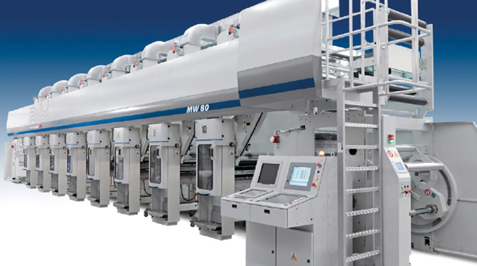
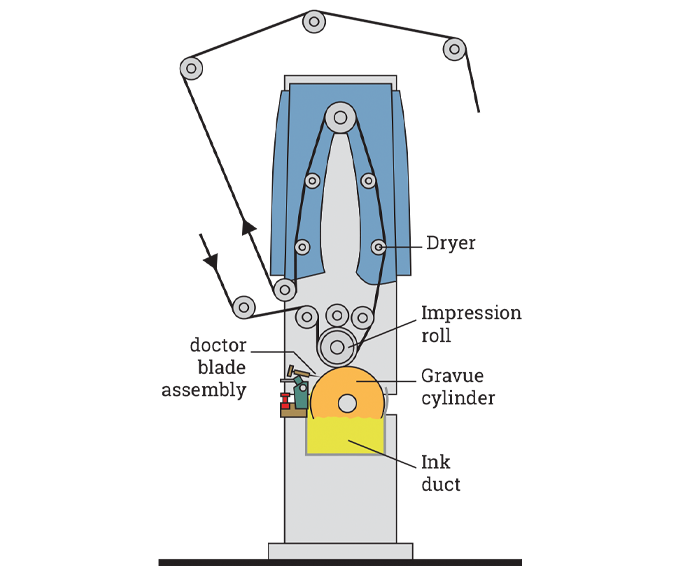
All the gravure press configurations used for self-adhesive label manufacture are in-line This means that there is a one printing unit per color and there are no real limitations on the number of printing heads used on an in-line press, (See Figure 7.1). One of the major differences between the in-line gravure press and the in-line litho and flexo presses is the position of the drying system.
The web path of the litho and flexo press travels downwards after leaving each printing head. This takes the web through the infra-red or UV drying units which are positioned ‘below’ the print unit.
The drying heads on the gravure press are positioned ‘above’ each print head which means that the web will travel upwards after leaving each printing head.

Figure 7.1 - Modern gravure printing press. Source- Bobst Rotomec
SINGLE GRAVURE UNITS
This type of gravure unit is usually incorporated into a dedicated in-line litho or flexo press or a multi-process platform press. The units, which are in a fixed position, are located in the press to give the best position to achieve the optimum printed result for highly reflective metallic inks and special coatings.
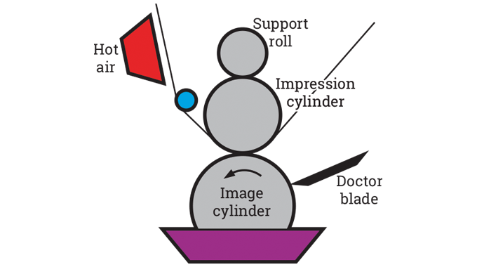
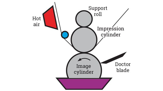
In Figure 7.2 you can see the configuration of the gravure unit of the type used in a multi-process combination press with the web, after printing, traveling upwards into the drying head and then passing downwards over a chilled roller and then into the next print unit for printing the next color.

Figure 7.2 - Principles of gravure process
PRINCIPLES OF PROCESS
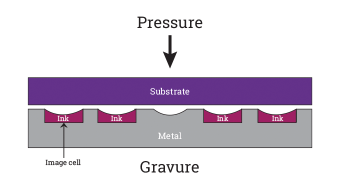
Unlike letterpress and flexo printing which are relief processes, the gravure process prints directly onto the substrate. The image is transferred directly to the substrate from the recessed image which is etched onto the gravure cylinder (See Figure 7.3).
The gravure cylinder revolves in a liquid ink with the ink being applied to the whole of the imaged print cylinder i.e. there are no inking rollers, ink duct or anilox rollers used in the gravure unit.

Figure 7.3 - Principles of gravure process
A doctor blade assembly holds the doctor blade, which is in constant contact with the rotating print cylinder. The ‘doctoring’ action removes the surplus ink from the non-image areas leaving fresh ink in the cell cavities.
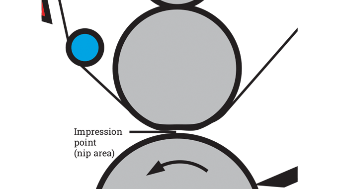
The doctor blade is positioned close to the point where the two cylinders are in contact with the substrate which is sandwiched between these cylinders. (See Figure 7.4). This is called the ‘nip' area and is the point at which the ink from the recessed cells is transferred to the substrate.

Figure 7.4 - Close up of point of p
A doctor blade assembly holds the doctor blade, which is in constant contact with the rotating print cylinder. The ‘doctoring’ action removes the surplus ink from the non-image areas leaving fresh ink in the cell cavities.
The doctor blade is positioned close to the point where the two cylinders are in contact with the substrate which is sandwiched between these cylinders. (See Figure 7.4).
This is called the ‘nip' area and is the point at which the ink from the recessed cells is transferred to the substrate.
The impression roller applies the downward force to the print cylinder. This impression roller is also in contact with an additional roller called the ‘support roller’ which gives additional support to the impression roller. (See Figure 7.2).
The surface of the impression roller is rubber covered and the ‘shore hardness’ of the rubber can be varied to increase or decrease the dwell time ensuring that there is maximum dwell at the point of contact between the substrate, impression cylinder and the image cylinder. The type of shore hardness will vary with the type of substrate being printed.
After the printing sequence the web then travels upwards into the dryer system, and it is important that the liquid ink is completely dry before the next printing sequence.
The transfer of the ink from the cell to the substrate is a capillary action. It is important that the ink is fully transferred from the cell and there is no residual dried ink left in the base of the cell. One of the problems with the gravure process is a printing defect called ‘dot skipping’ and results in halftone dots being missed on the printed image.This is a result of a poor transfer of ink from the image cells to the substrate. The ink transfer can also be influenced by the absorbency of the substrate being printed.
Some gravure presses are equipped with an electrostatic assist system which operates by creating a positive and negative static charge between the ink and impression roller and the image cylinder which can assist in giving a smoother and more complete transfer of the ink from cell to substrate.
Electro assist generates an electric field in the ‘nip’ area.
The chemical composition of the gravure ink can also influence the effectiveness of the electro-static assist system.
Gravure printing can also be affected by the type of substrate being printed; a smooth surface allows a better contact between the image cells and the substrate surface giving a better ink transfer and less dot skipping.
A rougher and less smooth substrate can have an adverse effect on the ink transfer resulting in missing dots and poor print. Electro-static assist systems do offer the gravure printer some excellent benefits including improvements in print quality on less expensive stock, faster press speeds and less substrate waste.
IMAGING THE GRAVURE CYLINDER
There are three methods of imaging the gravure cylinder;
-
Traditional method photographically using carbon tissue and acid etch called chemical etching
-
Mechanical engraving
-
Laser engraving
The gravure cylinder comprises of a steel base, then a layer of copper and finally a polished chrome surface which is applied after the imaging process.
The image area on the cylinder is produced by engraving a cell formation that differs in depth and size.
This variation in the cell structure controls the amount of ink and therefore the strength of color being printed, because the ‘cell size’ or ‘dot size’ can be engraved to a very small specification, subtle variations in dot/tonal detail and color strength can be easily produced.
The use of chemical etching for gravure printing within the label industry is very limited and this article will focus on the two main engraving systems used today i.e. mechanical and laser.
MECHANICALLY CUT CYLINDERS
The mechanical engraving of gravure cylinders started around the 1960s and is called a Klischograph system. This method of engraving requires the image cylinder to be revolving while a diamond tipped stylus, which is oscillating at 4000 times a second, pierces the surface of the image cylinder.
Every time the stylus penetrates the copper it removes a chip from the surface creating a cell shaped indentation. The deeper the stylus penetrates, the larger the cell, the lighter the penetration the smaller the cell.
The image to be engraved is scanned and the data is digitized. The digital information controls the engraving section of the machine. The depth of penetration of the stylus is controlled by the digital information and follows the tones and densities of the original artwork.
The cell structure of the mechanically engraved cylinder is governed by the shape of the stylus head and is a four sided pyramidal shape, the same as the cell formation on the mechanically engraved anilox rollers used in flexo printing. (See Figure 7.5).

Figure 7.5 - Typical gravure cell formation
LASER ENGRAVED GRAVURE CYLINDERS
Direct laser engraving for gravure cylinder imaging is now widely used in the commercial, packaging and label markets.
Direct laser engraved cylinders are imaged using a laser engraving unit that is controlled by a digital file. The file contains all the data required to reproduce the exact tonal values and detail that are required for the correct image reproduction. Laser engraving removes the problem of image inconsistency when a duplicate cylinder is required.
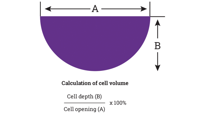
The cell shape of the laser engraved cylinder differs from the mechanical system. Whereas the mechanical cell is a pyramid shape, the laser is a scoop shape. The depth and width of the cell determines the volume of ink delivered (see Figure 7.6).

Figure 7.6 - Cell shape and ink volume
Gravure imaged cylinders or sleeves are manufactured with a copper outer surface on a steel base, If the cylinder is to be imaged with a mechanical engraving system then the copper layer is sufficient, however if the cylinder is to be direct laser engraved then an additional zinc layer is required.
The laser engraves directly onto the zinc surface of the cylinder and is considerably faster than mechanical engraving, producing a cell formation at 70,000 cells per second. The facility to produce varying cell size and also cell shapes means that the cells can be tailored to produce very high resolution tonal values, particularly for vignettes with no ‘saw edge’ effect on small text and a much improved ink transfer.
After the engraving process is completed it is necessary to chrome the cylinder surface.
This process of chroming gives the image cylinder a much harder surface, extending the life of the cylinder image and improving the doctoring process by ensuring that all the surplus ink is removed from the surface of the non-image area.
THE DOCTOR BLADE
As previously explained the image cylinder rotates in the ink duct coating the whole surface of the image cylinder with liquid ink including the image cells.
The ink on the non-image area is ‘doctored’ clean (wiped) by the doctor blade which is positioned over the cylinder (See Figure 7.7) at a point just prior to the nip area. The positioning of the doctor blade assembly is important.
Because gravure inks are a solvented system and dry very rapidly, it is necessary to keep the distance between the doctoring process and the print ‘nip’ to a minimum, ensuring that the ink remains as open and liquid as possible.

Figure 7.7 - Location of docter blade on gravure unit
The gravure doctor blade unit is far more sophisticated than the type used in the flexo system.
The angle of attack to the cylinder can be adjusted from a 90 degree angle to a much sharper 45 degree angle and this facility allows the printer to achieve the optimum position for a clean wipe and the best possible printed result.
The thickness of the doctor blade can also be varied to assist in achieving the best doctoring result.
By varying the thickness of the doctor blade the printer can also control the volume of ink left in the cell. A thinner blade removes slightly more ink from the cell and albeit this is a very small amount it can slightly reduce the density of the color being printed.
The steel doctor blade is supported by a backing blade to give better stability. Traditionally the doctor blade would be removed and re-sharpened by the printer using an oiled stone, and this would be done at intervals throughout the print run. However the modern doctor blade is now a replaceable item which removes the need for re-sharpening by hand.
GRAVURE INKS AND DRYING SYSTEMS
The majority of inks used in the gravure process are solvent based, however there are some gravure printed self-adhesive labels that are printed using UV gravure inks.
Solvent based inks require infra-red and/or hot air drying to drive off the solvent content. Because the inks are liquid and very fast drying it is necessary for the ink to be constantly circulated through the ink weir, ink trough and the ink pumping system.
Maintaining the correct ink viscosity is critical and the viscosity readings can be made manually or automatically.
Adjustments can be made to the speed of the ink drying by the introduction of a faster or slower drying solvent, however this adjustment must be done under tight control as it is important that the correct balance of the solvents which make up the ink formula is maintained.
Gravure inks can be formulated using different types of solvent systems and the printer must ensure that any solvent used is of the correct system.
The drying system on the gravure label press differs from the systems used on litho, flexo and screen presses. The drying unit is positioned above the print unit meaning that after the print sequence the web travels upwards into the dryer. (See Figure 7.8).

Figure 7.8 - Gravure unit showing drying head
IDENTIFYING THE GRAVURE PROCESS
The gravure process can be easily identified by the saw tooth or serrated edge visible on the printed text and on the edges of solid color areas.
This saw edge is a characteristic of the process and is created by the outer edge section of the individual cells which make up the image. The screen process has a similar characteristic. Gravure and screen imaging cannot produce ‘half a screen’ and therefore cannot produce a straight edge.
However, this is not the case with laser imaged cylinders as the laser can engrave half a cell, producing a straight edge.This control over the engraving process illustrates the level of print quality that can be produced by the gravure process.
Another method of identifying the gravure process is the reticulation that can occur within the solid area of the print.
Reticulation can be created by inks that are either too thin in viscosity or the solvent balance is incorrect.
ADVANTAGES OF THE GRAVURE PROCESS
-
Sheet or web-fed application
-
Excellent print quality - excellent sharpness and reproduction
-
Precise inking with no color variation throughout the print run
-
Consistent and substantial ink film weight
-
Wet on dry - excellent half-tone reproduction
-
Long cylinder life - making repeat runs very economical
-
Suitable for food packaging
-
Most suitable process for printing of metallic inks
-
Gravure cylinder sleeve option
-
Laser engraving high quality - 70,000 cells per second variable screen
-
Exact cylinder/image replication
DISADVANTAGES OF THE GRAVURE PROCESS
-
High preparatory and origination costs, but due to improved technology these have reduced
-
High capital cost of press
-
Most gravure ink systems solvent based (environmental issues)
GRAVURE PRINTED APPLICATIONS
-
Self-adhesive labels. filmic – paper – metallic
-
Flexible packaging and shrink sleeves
-
Magazines/catalogues/books
-
Security printing eg stamps, banknotes, bonds,
GRAVURE – SUMMARY
Gravure has traditionally been used as a long run process for wet-glue labels.
More recently it has made inroads into narrow and mid-web presses for self-adhesive labels where the ability of gravure to apply varnishes , lacquers and top coatings offers particular advantages.
Gravure units are typically added as part of a combination press configuration.
DEVELOPMENTS IN METALLICS
Gravure is an excellent process for applying metallic inks and finishes with a high level of lustre.
Developments exist where vacuum metallised particle inks are reverse printed by the gravure process onto a clear substrate, such as a PP.
This method gives a very bright and highly reflective appearance resembling that of foil blocking. The metallised particles are easily suspended in the solvent medium used in the gravure process and align smoothly and easily to the clear label substrate.
PLATE SYSTEMS
Photopolymer plate systems for gravure have been developed as well as computer-to-cylinder systems.
An ‘etched’ polymer plate can be produced with indentations of varying depth which ‘hold’ the ink.
Depending on the quality, the resulting print may look similar to, or the same as those produced with the traditional photogravure process using etched cylinders.
More recently a direct digital laser etching process has been introduced, which will eventually reduce the cost of imaging gravure cylinders.