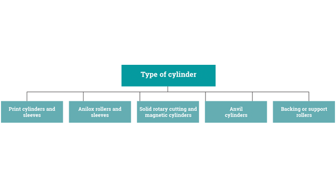
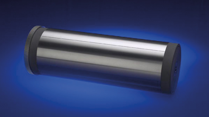
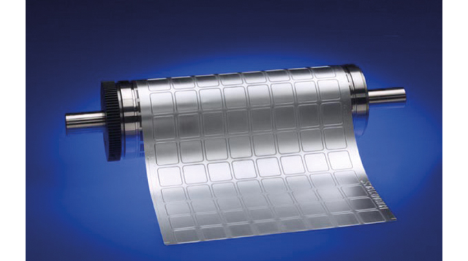
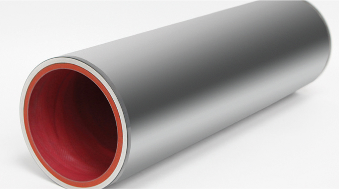
Figure 7.1 - Types of cylinders, sleeves and rollers used in label printing and converting
Key to the performance of much of the label printing and converting process is the manufacture, quality and operation of the many different types of cylinders, anvils, sleeves and rollers that are used, together with all the associated bearers, shafts, gears and frames. This article examines some of the main cylinder types used in the industry in rather more detail, as can be seen in the following flow chart.
In flexographic, offset litho, gravure, semi-rotary and rotary letterpress printing, the term 'cylinder' normally refers to the rollers on which the printing plates are mounted (plate or print cylinders). In offset litho there is additionally a cylinder that carries a blanket (blanket cylinder) onto which the plate prints and then transfers or ‘offsets’ the printed image onto the printing substrate. As can be seen in the Figure 7.1 diagram, in addition to print cylinders, other examples of cylinders and sleeves used in the labeling industry are: print sleeves, anilox rollers or sleeves, solid rotary cutting cylinders, magnetic cylinders, anvil cylinders, backing rollers or support rollers.
Before going on to examine these different types of cylinders and rollers in rather more detail, it would be useful to look at the various elements that are common to many of them and their relative positions in relation to each other. Figure 7.2. shows a typical die, magnetic, or support cylinder and its key components.

Figure 7.2 - Components of a typical cylinder
Bearers are the areas that provide a smooth rotary movement for cylinders that come into contact with each other during printing and die-cutting.
They are typically placed on outer edges of printing or cutting areas. During the printing process, they can minimize plate bounce and over impression by helping to carry part of the impression pressure or load. In the die-cutting process, they support the cutter against the anvil and provide sufficient space between the peak (top) of the cutting edge and the surface of the anvil to ensure adequate penetration of the cutter.
Where bearings are part of the design, they can be subject to wear and it is advisable that replaceable parts are held available to avoid any disruption in the event of a breakdown. Press and converting units are subject to stresses and strains caused by the use of heavy tooling, continuous running and potentially inadequate maintenance. Cylinder bearings have a limited life so regular maintenance should be in place, including cleaning, checks for wear and adequate lubrication.
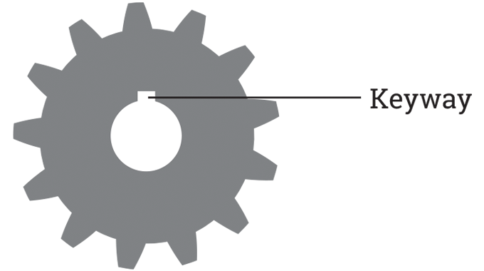
Shaft. Printing and cutting cylinders may have the shaft as a permanent part of the cylinder body, or have a removable shaft, bearers and gears. Where shafts are removable there will normally be a key and keyway (Figure 7.3.) to connect the cylinder various parts together. This whole system is called a keyed point. This keyed point still allows relative axial movement between the parts.

Figure 7.3 - A sprocket/gear with an internal parallel keyway
A shaftless drive is one in which the mechanical drive shaft has been replaced by an electronic drive shaft and where single driven (servo) motors are in use.
Gears. When gears are manufactured it is intended that they should be meshed at a certain depth with the gear they are driving. When meshing the printing or cutting cylinder gear with the adjacent roll gear, the diameter is critical to accurate registration. Too deep or too shallow a mesh in the print station may cause loss of register between one color and the next. Regular lubrication of gears is preferred to intermittent applications, as this will maintain a constant film of oil and even out temperature fluctuations.
Cylinders are made using mainly an aluminum material but steel is possible. They are supplied with the standard gears in high accuracy or with hardened and ground gears. There are treatments available to protect various cylinder surfaces. As the norm, cylinders are supplied with the gears and may include additional components such as shafts, bearers, register rings and other elements as required.
CYLINDER AND ROLLER PRODUCTION
Cylinders used in the label printing and converting process are mostly machined from solid materials on CNC milling machines. Milling machines are often classed in two basic forms, horizontal and vertical, referring to the orientation of the main spindle. Both types range in size from small, bench-mounted devices to room-sized machines. Unlike a drill press, which holds the solid tool stationary as the drill moves axially to penetrate the material, milling machines also move the solid tool radial against the rotating milling cutter, which cuts on its sides as well as its tip. Solid tool and cutter movement are precisely controlled to less than 0.0001” / 0.00254 mm).
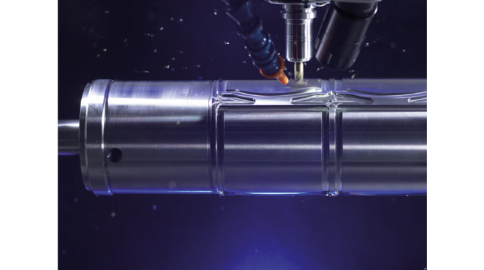
CNC milling machines can perform a vast number of operations, from simple (e.g., slot and keyway cutting, planing, drilling) to complex (e.g., cutting lines, embossing patterns, etc.). Cutting fluid is often pumped to the cutting site to cool and lubricate the cut and to wash away the resulting swarf (See Figure 7.4).

Figure 7.4 - CNC milling of a cylinder. Source- RotoMetrics
There are a wide variety of milling machines available, including multi-axis machines in which CNC controlled tools move in four or more ways, manufacturing parts out of metal by milling away excess material. Multi-axis machines also support rotations around one or multiple axes.
Final finishing operations on milled cylinders are likely to include processes such as cylindrical grinding and polishing.
PRINTING CYLINDERS (PLATE CYLINDERS)/PRINTING SLEEVES
Printing cylinders. Standard printing cylinders form the basis of every label printing machine and are manufactured with the greatest care in order to guarantee optimum fit and run-out accuracy.

Figure 7.5 - Printing cylinder with bearers and gear wheel. Source- RotoMetrics
In the flexographic, letterpress and litho processes, the printing plates are located on the print cylinders. Each cylinder needs to have accurate and even contact with the inking rollers and the surface of the substrate. In the case of the litho process, accurate and even contact is with the offset blanket. All print cylinders should run perfectly true with an accuracy of .0001” / .0025 mm ensuring that the pressure on the adjacent rollers is consistent. The diameter of the printing cylinder must be corrected to compensate for the thickness of the printing plate and mounting tape.
Printing cylinders (Figure 7.5) used in the roll-label industry include plate cylinders, blanket cylinders and impression cylinders. These are made from solid aluminium or steel, or produced as a tube with end rings fitted.
Cylinders may have spur or helical gears, no less than AGMA Class 9 for precision and quAdded-value protection can be provided with various coatings for the surface of the cylinder. For print cylinders, anodizing or other hard surface treatments can prevent scratches or damage during demounting of the printing plates. If required, they can be provided with a range of non-corrosive hard wearing surfaces.
For cylinders with bearings, the bearing quality is critical for fine process printing. When ordering plate cylinders, convertors should be aware that not all bearings of the same size or product code are of the same quality.
Choose a supplier who has tested and proven the quality of the bearers that they utilize.
Printing cylinders may be refurbished and treated/re-treated with a range of hard wearing and non-corrosive surfaces to suite particular applications. During refurbishing, shafts and journals are checked and closely inspected for fatigue or wear and refurbished or replaced to restore them to their original condition.
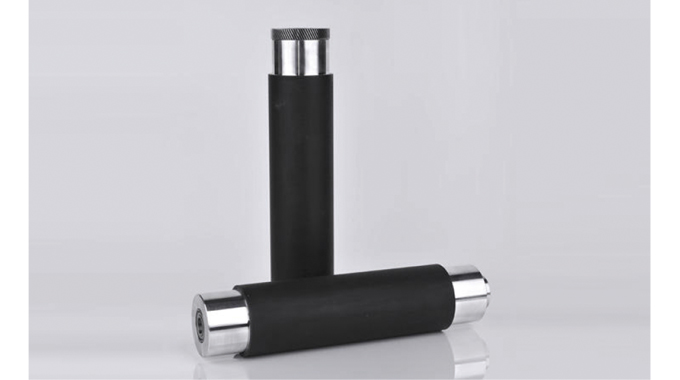
Coated cylinders. There are a number of suppliers that offer unique coatings that can be applied directly onto existing or newly manufactured cylinders. The coatings provide a platform for a plate that will enable consistent impression, so eliminating a huge variable of the flexo process. See Figure 7.6 above for an example of a coated cylinder.

Figure 7.6 - Shows an example of a rubber coated cylinders. Source- Rotometal Company
Printing plates are mounted directly to the standard cylinder with double sided tape. The most commonly used tape thickness is .015” / 0.381 mm but others are available.
Rubber coated cylinders are also available as varnish, lacquer and lamination cylinders. The type of rubber and its degree of hardness ordered according to customer request.
Printing cylinder sleeves. A conventional printing cylinder normally consists of the cylinder shaft with bearing system, a gear and the printing cylinder body.
Such cylinders, depending on the printing length, may be quite heavy, somewhat awkward to handle, and may require considerable maintenance. Special bearing options are needed and great care needs to be taken when inserting such cylinders in the press.
Other designs may include a lightweight print cylinder sleeve made up of one single component. Its bearing system is straightforward and extremely easy to insert into the press. In addition to this easier handling, printing cylinder sleeves also save a great deal of time during setup and immediately after the print job.
The printing cylinder sleeves are designed to move into the sleeve changing position at the touch of a button, and the change itself will take just a few moments. While the new printing cylinder sleeve is still moving into position, a direct servo drive will be presetting the print registration.
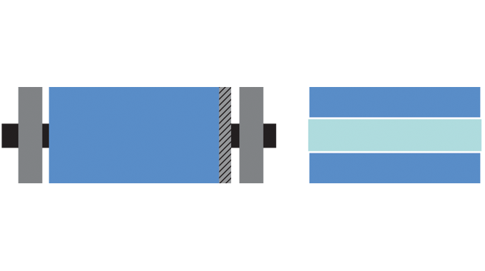
A particular advantage of printing cylinder sleeves is that they do not have gears (see Figure 7.7), thereby eliminating the gear marks that tend to appear in the print image over time. Gear wear may often be the culprit when experiencing gear marks in the print.

Figure 7.7 - On the left, a conventional printing cylinder with gear and bearer rings; on the right, a printing cylinder sleeve
Printing cylinder sleeves that do not have gears have a significant advantage during printing. Over time, changing gear combinations – such as those between printing and impression cylinders can result in gear marks (called ‘barring’) appearing in the print image. With conventional printing cylinders this barring may have a variety of causes but one could be different degrees of wear or even very slight damage to the teeth of the printing or impression cylinder gears. This can be explained using Figure 7.8 below.

Figure 7.8 - Comparison between geared printing cylinders and servo driven cylinder sleeves
The diagram on the left shows a conventional printing cylinder with gears. This print cylinder cannot perform independent register corrections. There are other designs, however, that adjust the geared anilox to the geared print cylinder for registration moves with no impact on the web tension. The printing cylinder sleeve on the right, though, is able to perform register corrections without the impression cylinder (no impact on the web tension).
The printing cylinder sleeve makes systematic use of the benefits offered by a press’s state-of-the-art servo drive concept. In conjunction with a chambered doctor blade and anilox roller sleeve, this concept enables extremely quick job changes and highly reliable processing of a wide range of substrates.
Originally developed for mid/wide-web flexographic printing, printing cylinder sleeve systems are also now used in narrow-web label printing. Making all this possible was the introduction of servo technology, paving the way for the industrial use of synthetic printing cylinder sleeves, with a number of suppliers offering different sleeve constructions.
Synthetic printing cylinder sleeves are considerably lighter, can be manufactured at competitive prices, and make larger printing cylinders much easier to handle. Composite sleeves with hard inner and outer shells made of plastic have been particularly successful in establishing themselves in the market. In most cases, the sleeve itself mostly consists of a two-component plastic foam.
These systems are very light and can be manufactured at competitive prices, but they tend to age and are not necessarily resistant to solvents or cleaning agents.
Over time, the printing cylinder sleeve thus loses its original dimensional accuracy having a significant impact on print quality. Depending on printing requirements and frequency of use, the service life of a synthetic printing cylinder sleeves can be anything from just a few months to 2-3 years. After this, the sleeve has to be replaced. Alternate designs are available that incorporate an inner synthetic sleeve and an outer aluminum shell. This design can greatly improve the life of the sleeve cylinder making it more comparable to the life of a hard-coated aluminum print cylinder.
Aluminum printing cylinder sleeves are only marginally heavier than their synthetic counterparts, but are extremely precise and robust. They are fitted onto a high-precision printing cylinder shaft and held in place by a clamping system at the touch of a button. Unlike synthetic printing cylinder sleeves, the aluminum sleeve does not age and retains its dimensional accuracy over its entire service life. What's more, with good care and handling, there is very little wear-related ageing or maintenance with aluminum sleeves, making them a potential one-off investment.
ANVIL CYLINDERS/ROLLERS
Anvil cylinders are hardened steel rollers upon which the bearers of a rotary die, magnetic cylinder or perforation cylinder run. Normally, this cylinder is placed in the bottom position of a die station. However, for certain jobs it is necessary to place the anvil roller in the top and the cutting cylinder in the bottom position. Most often there is a roller under the anvil, called a support roll.
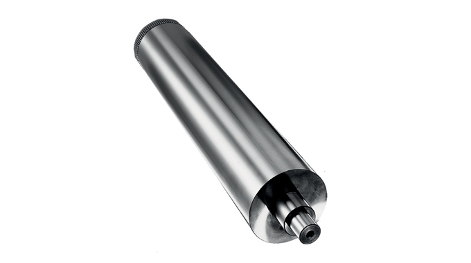
Anvil cylinders (Figure 7.9) are characterized by their exemplary hardness and run-out accuracy, whether in use as a standard diameter cylinder or with a plus or minus body diameter (called a ‘stepped’ anvil). Together, these anvils can compensate for a wide range of backing materials. They are quality tools that guarantee success. They are available for all machine types, in all standard designs and, of course, special designs are also possible (based on drawings or samples). Straight anvils are used for most standard daily operations, and stepped anvils provide the flexibility to run dies on liners other than those for which they were made. For some materials, most often paper, the stepped anvil can be used to compensate for worn cutting tools, extending the life of a die when most needed.

Figure 7.9 - A typical anvil cylinder. Source- Kocher+Beck
The hardness and the finishing (roughness) of an anvil roller will normally be specified in the drawing of a machine-supplier. The base materials used for anvil cylinders are high quality vacuum hardened tool steel or case-hardened steel. The manufacturing process involves sawing/turning the steel bar, milling of the keyway, cutting the gears and vacuum or case hardening the cylinder, case hardening the gear, cylindrical grinding and polishing of the cylinder.
SUPPORT ROLLERS
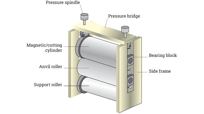
These are cylinders/rollers which are positioned below the anvil cylinder in the cutting unit of a roll-label press. They support the anvil and cutting cylinder, relieving the pressure and weight of the tools off the journals of the anvil (Figure 7. 10). Having a support roll can decrease problems with flex (deflection) in the cutting cylinder when increased pressure is applied.

Figure 7.10 - Shows the relative positions of anvil, support, and magnetic cylinders/rollers in a cutting unit
MAGNETIC CYLINDERS
Magnetic cylinders used with flexible dies provide an economic alternative to standard rotary die-cutting tools. They are manufactured on CNC machines from high tensile and high alloyed stainless tool steel with fully hardened bearers. Hard ferrite or ceramic and rare earth permanent magnets, hardened bearings seats as well as bearing necks with fully hardened centering sleeves are usually standard. Higher-strength magnet configurations are available based on the application.
Magnetic cylinders are precision-engineered to optimize flexible die accuracy. The combination of flexible dies with permanent high-adhesion magnetic cylinders (Figure 7.11) ensures accuracy even in the most challenging applications, allowing converters the opportunity to increase profitability. Magnetic cylinders are available for a full range of label presses and converting machinery, allowing converters to use flexible dies in many different applications.

Figure 7.11 - Magnetic cylinder and flexible die. Source- RotoMetrics
Excellent cutting results not only require an accurate flexible die. A true-to-size magnetic cylinder is equally vital. Ideally, to optimize performance and life, the circumference of the magnetic cylinder as well as the anvil cylinder is recommended to reach at least the maximum working width of the press. Basic requirements for label production on thin PET liners are magnetic and anvil cylinders with .0001” / 3µm run out accuracy.
The bearings of the magnetic cylinders, the anvil cylinder and their substructure, as well as the general stability and stiffness of the cutting unit are all things to take account of to achieve accurate die-cutting, especially with thin liners.
Suppliers of magnetic cylinders are able to offer a range of services to refurbish and repair cylinders, including magnet repairs, bearing replacement, gear replacement and cylinder grind-overs. Anvils can also be reground to within microns and generally be brought back to specifications.
ANILOX ROLLERS
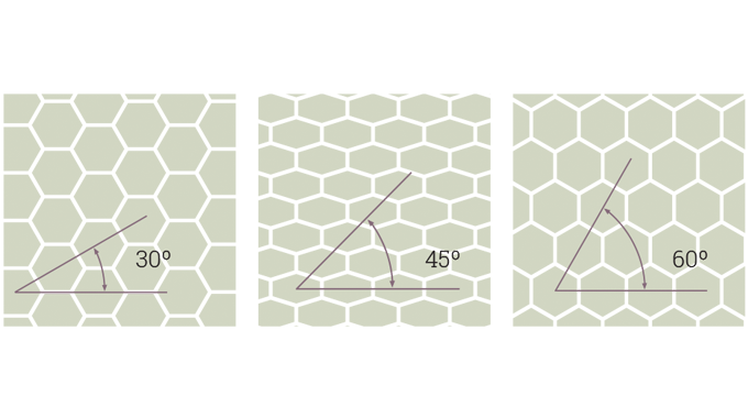
Anilox rollers are engraved or ceramic-coated rolls used to meter ink to the raised (image) areas on the relief printing plate used in the flexographic inking system. Each type of flexographic press uses an anilox roll, the surface of which is engraved (Figure 7.12) at one of three angles with a pattern of tiny cells of fixed size and depth that transfer the ink to the plate. The cells are so small that they can only be seen under magnification.
The size and number of these cells determine how much ink will be delivered to the image areas of the plate, and ultimately to the substrate. An anilox roll today is either copper engraved and chrome-plated, or ceramic-coated steel with a laser-engraved cell surface.

Figure 7.12 - Anilox cells are engraved at one of three angles- 30˚, 45˚ or 60˚
There is also some use today of anilox sleeves. These are not new. They have been under development, testing, trials and use for a number of years, with many manufacturers of ‘gearless’ presses particularly looking at the benefits of sleeve technology, such as ease of register, overall quality, low weight, maintenance, etc, as well as lower shipping costs and storage capabilities.
Although early attempts at anilox sleeve manufacture were somewhat hit-and-miss due to a variety of reasons there have subsequently been dramatic improvements in the material, construction and stability of anilox sleeves.
In use, anilox sleeves (Figure 7.13) need to be expanded to fit securely on the press mandrels. This may be undertaken with a mechanical mandrel that expands by hydraulic action, or through the use of a press mandrel with an inner compressible layer, or bladder, that is activated by air.

Figure 7.13 - An anilox sleeve. Source- Harper
Mandrels used with anilox sleeves are critical to the success of the process, with diameter, circularity and concentricity all important.
It is usual to specify anilox rollers or sleeves by a line screen count: the number of cells in a given linear distance. The higher the line screen count the greater the number of cells, and the smaller the cell size. The smaller the cells, the smaller the volume of ink carried in the cells. The depth and shape of the cells is also a factor in the efficient delivery of a uniform ink film to the printing plate. Cell depth ratios are critical in choosing the right anilox roller for a particular application. To avoid anilox moiré, film or plate screen angles should be at least 7.5° away from the anilox cell angles.
The line screen count of anilox rollers and sleeves – expressed as lines per cm or lines per inch – determines the resolution of the printing. Cell depth is generally measured in microns and, when related to the cell’s opening, produces a depth-to-opening ratio. The most efficient producing a depth-to-opening ratio between 20 and 25 per cent.
Anilox tools are carefully selected for specific types of printing, substrates, and customer requirements. The printer may well perform test runs to determine the ideal anilox for producing the desired ink distribution for halftones, spot color and solids.